6.3. Electronic components
Here are presented basic tutorials for using main components of Arduino system
6.3.1. LED
6.3.1.1. Datasheet
6.3.1.2. Presentation
A LED (Light-Emitting Diode) is a diode (Diode) emitting light when crossed by a current.
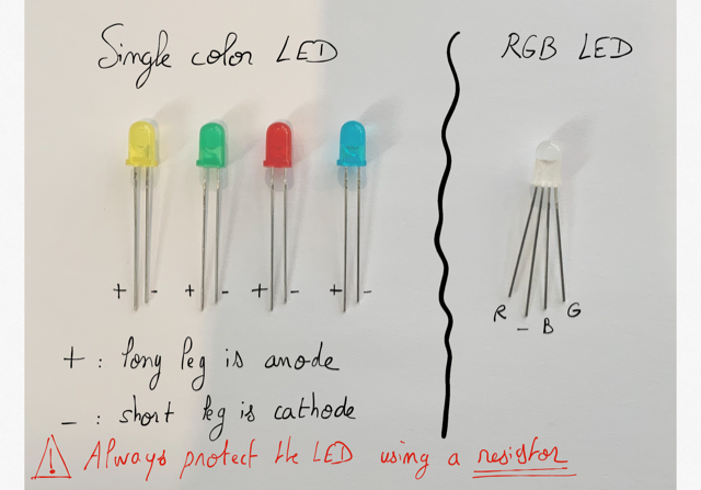
Figure 6.8: Different kind of LED.
6.3.1.3. Connection
Caution
A LED is a polarized electronic component that allow electricity to flow through it in one direction only. The long leg(Anode) should be connected to the + and the short leg (Cathode) to the -.
A LED should always be protected by a resistor.
The datasheet of a standart LED precognize a current of 20 mA and a voltage of 2V. Then it should be connected to a serial resistor depending of the source volatge.
How to determine the resistor ?
The formula for resistor is:
(6.1)
In the following example, if the source voltage is  , a resistor of 220
  should be added to the LED.
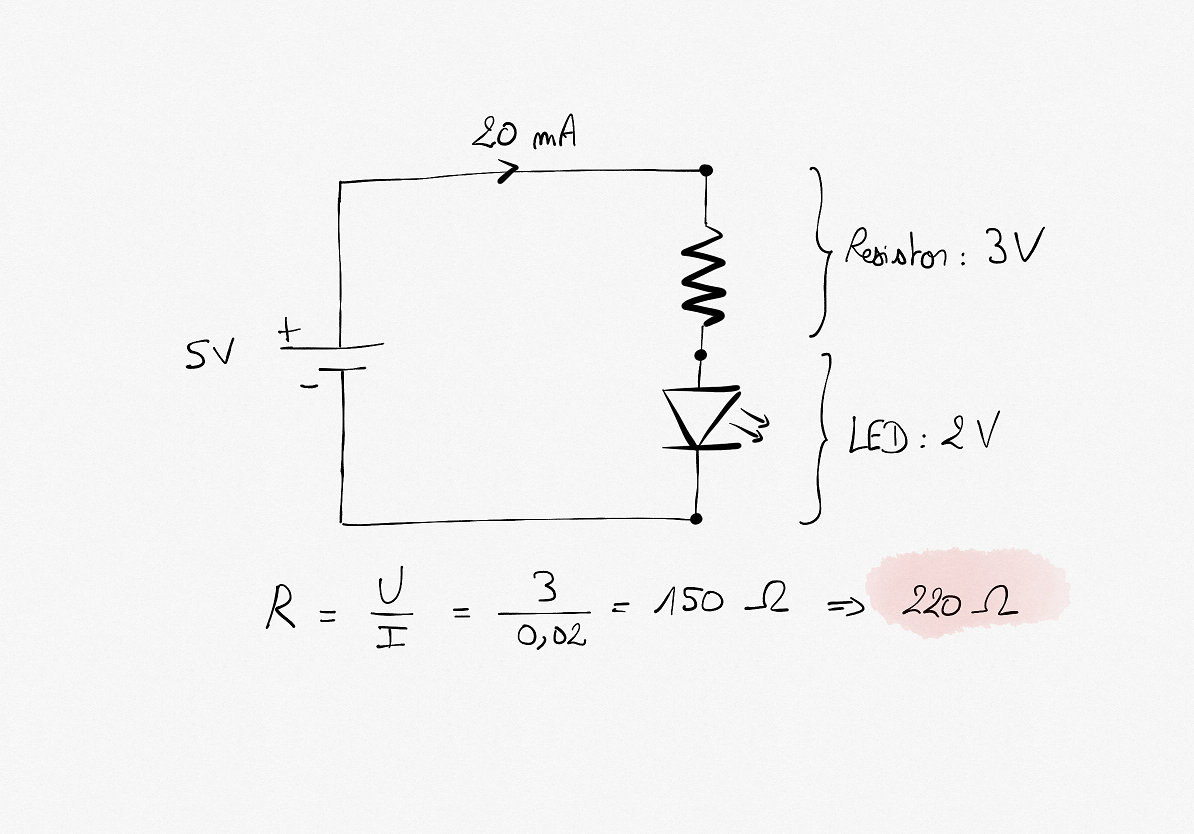
Figure 6.9: Direct connection of a LED using a resistor.
6.3.1.4. Example using Arduino
A LED can then be connected to a digital pin on the arduino UNO.
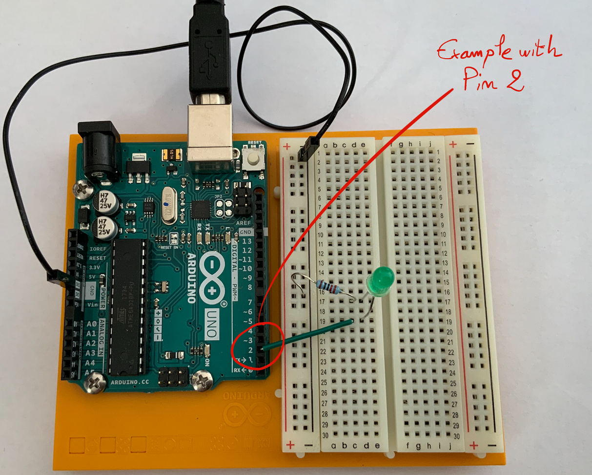
Figure 6.10: Connecting a LED to a digital pin.
An example of arduino code that could be uploaded in the microcontroller is shown below. In this example, the LED (connected to digital pin 2) turns on for one second, then turn off for one second, repeatedly.
1 2 3 4 5 6 7 8 9 10 11 | void setup() {
// initialize digital pin 2 as an output.
pinMode(2, OUTPUT);
}
void loop() {
digitalWrite(2, HIGH); // turn the LED on (HIGH is the voltage level)
delay(1000); // wait for a second
digitalWrite(2, LOW); // turn the LED off by making the voltage LOW
delay(1000); // wait for a second
}
|
6.3.2. Switch (pushbutton)
6.3.2.1. Datasheet
6.3.2.2. Presentation
A pushbutton connects two pins when they are pushed.
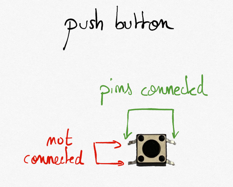
Figure 6.11: The pushbutton in the arduino UNO kit.
6.3.2.3. Connection
A pushbutton connects very simply:
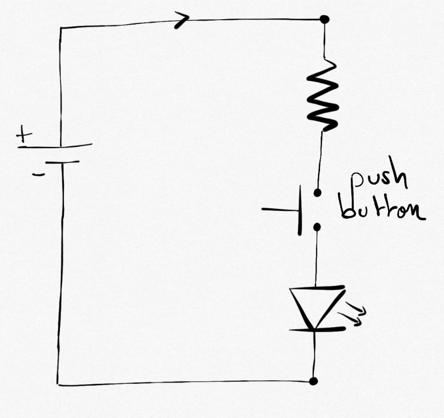
Figure 6.12: A pushbutton in a simple circuit containing a LED.
6.3.2.4. Example using Arduino
A pushbutton can be used to command the arduino UNO microcontroller as in the following example:
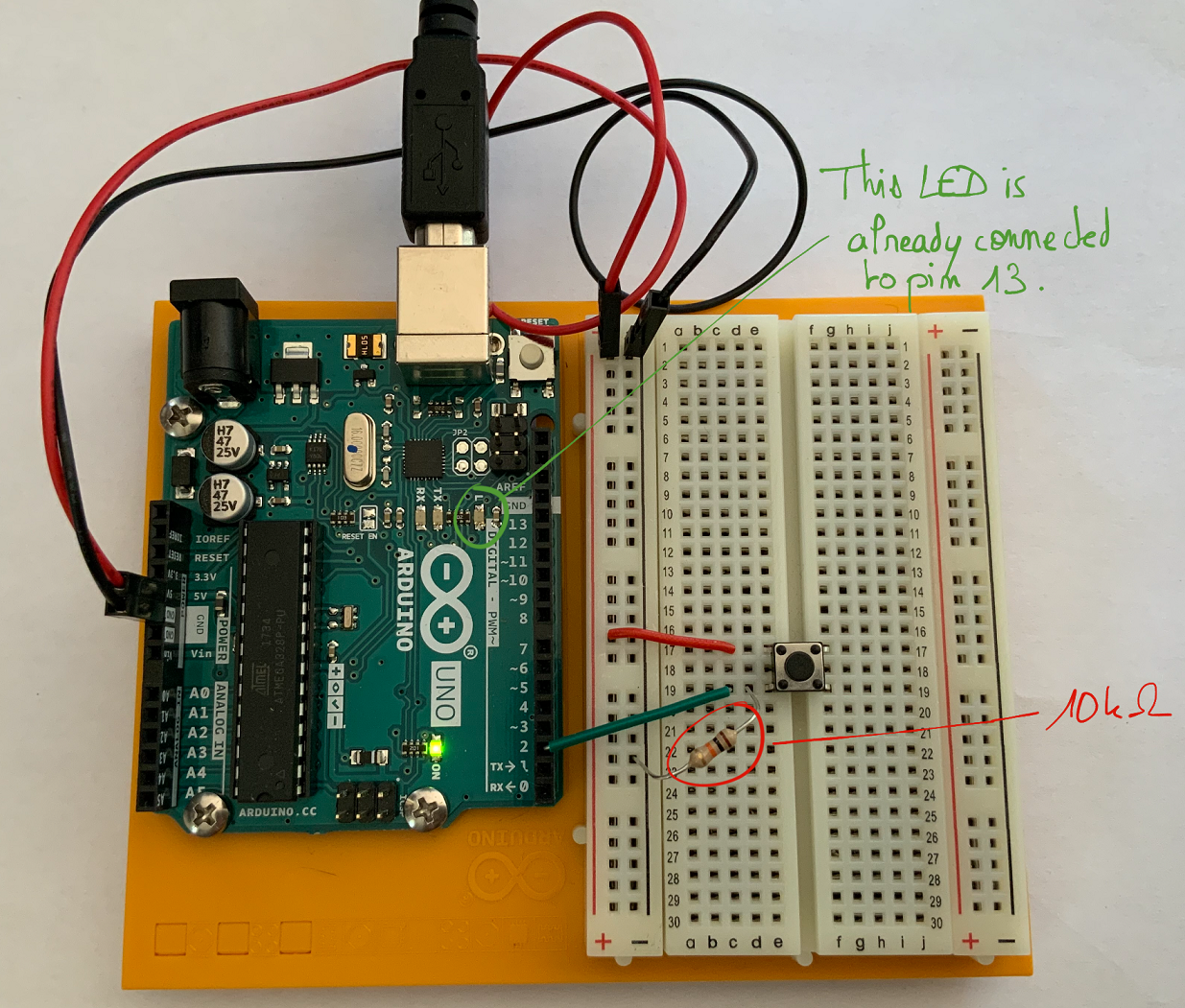
Figure 6.13: Connecting a pushbutton as input to a digital pin.
Note
Note that a pull-down resistor is added ( ) from ground to the switch. It ensure connection from ground to the pin when the pushbutton is open, allowing the input to read LOW when no voltage coming in throught the pushbutton.
An example of arduino code that could be uploaded in the microcontroller is shown below. In this example, the LED (connected to digital pin 13) turns on when the pushbutton (connected to pin 2) is pressed. No extra LED is added here because a LED on the board is already attached to pin 13 (L)
1 2 3 4 5 6 7 8 9 10 11 12 13 14 15 16 17 18 19 20 | void setup() {
pinMode(13, OUTPUT); // initialize the LED pin as an output:
pinMode(2, INPUT); // initialize the pushbutton pin as an input:
}
void loop() {
int buttonState;
// read the state of the pushbutton value:
buttonState = digitalRead(2);
// check if the pushbutton is pressed. If it is, the buttonState is HIGH:
if (buttonState == HIGH) {
// turn LED on:
digitalWrite(13, HIGH);
} else {
// turn LED off:
digitalWrite(13, LOW);
}
}
|
6.3.3. Temperature sensor
6.3.3.1. Datasheet
6.3.3.2. Presentation
The temperature sensor in the Arduino UNO starter kit is a TMP36 that outputs a changing voltage on its middle pin depending on the temperature it senses.
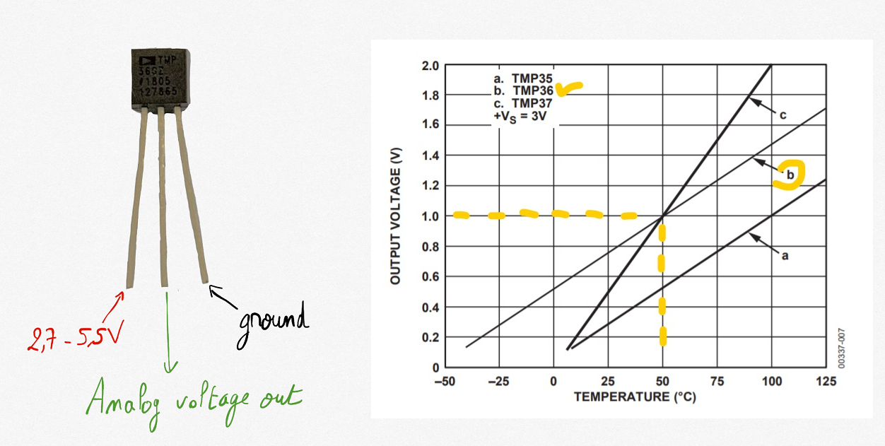
Figure 6.14: The TMP36 temperature sensor in the kit.
possible confusion
The TMP36 temperature sensor can be confused with a transistor. TMP is written on the flat side of the TMP36 sensor.
6.3.3.3. Connection
Looking for the flat facing face of the sensor, the left pin is connected to power, the right pin to the ground. The middle pin is linked to an analog input.
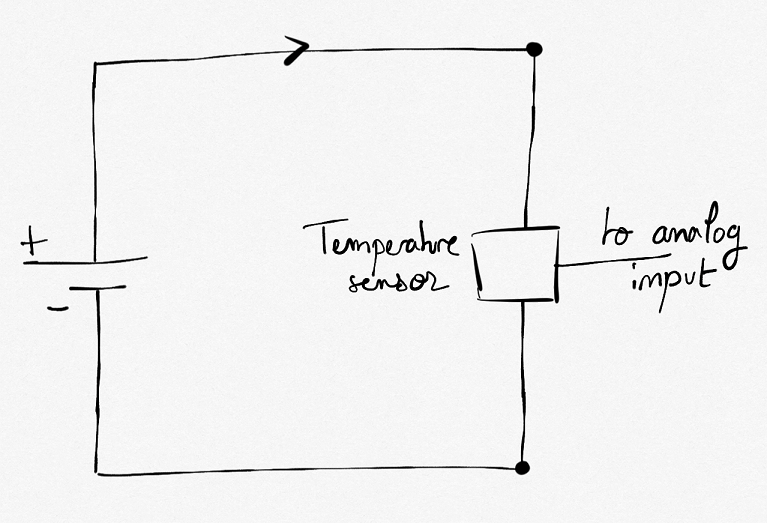
Figure 6.15: Connecting a TMP36 temperature sensor.
6.3.3.4. Example using Arduino
Connection to a analog pin to catch the voltage is possible with Arduino UNO board.
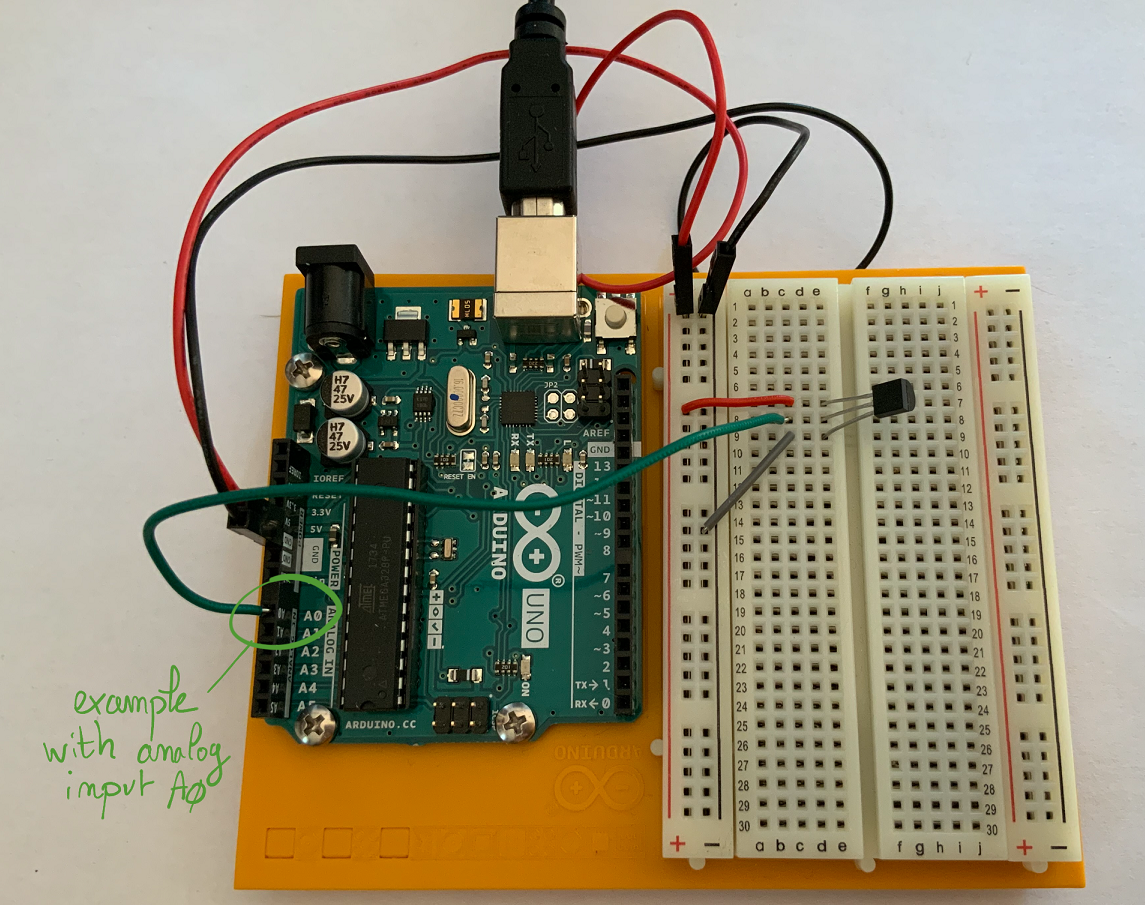
Figure 6.16: Connecting a TMP36 temperature sensor to an analog pin on the Arduino UNO board.
An example of arduino code that could be uploaded in the microcontroller is shown below. In this example, the analog input A0 catch the value of the sensor. The value that is between 0 and 1023 is a representation of the voltage on the pin.
1 2 3 4 5 6 7 8 9 10 11 12 13 14 | void setup() {
Serial.begin(9600); // initialize serial communications at 9600 bps:
}
void loop() {
int sensorValue; // value read from the TMP36
sensorValue = analogRead(A0); // read the analog in value:
// print the results to the Serial Monitor:
Serial.print("sensor = ");
Serial.print(sensorValue);
Serial.print("\n");
delay(200); //Wait 200 ms before the next loop
}
|
The value is printed on the serial connection between the board and the computer. It can be observed using the serial monitor (“Tools” -> “Serial monitor” in the Arduino application).
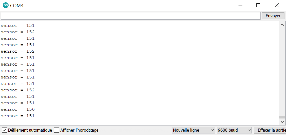
Figure 6.17: The serial monitor shown the value catch by the analog input each 200 ms.
Using the dataSheet, it is easy to transform the analog input voltage  in temperature with:
(6.2)
6.3.4. Photoresistor
6.3.4.1. Datasheet
6.3.4.2. Presentation
A photoresistor changes its resistor depending on the amount of light that hits it. In dark, the resistor is hight, and it decreases when light hits it.
6.3.4.3. Connection
It can be used together with a resistor to form a voltage divider.
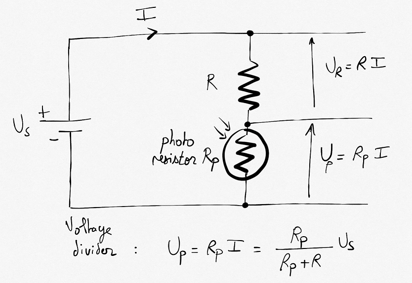
Figure 6.18: A voltage divider using a photoresistor allows to obtain a voltage variation with lights.
Choice for the resistor
Looking for the datasheet, one reads a maximum of  in the dark and typically
  for a
for a  light flux. Using a will ensure to range from nearly
  to
to 
6.3.4.4. Example using Arduino
The voltage at the point between the photoresistor and the serial resistor can be mesured by connection to an analog input of the Arduino board.
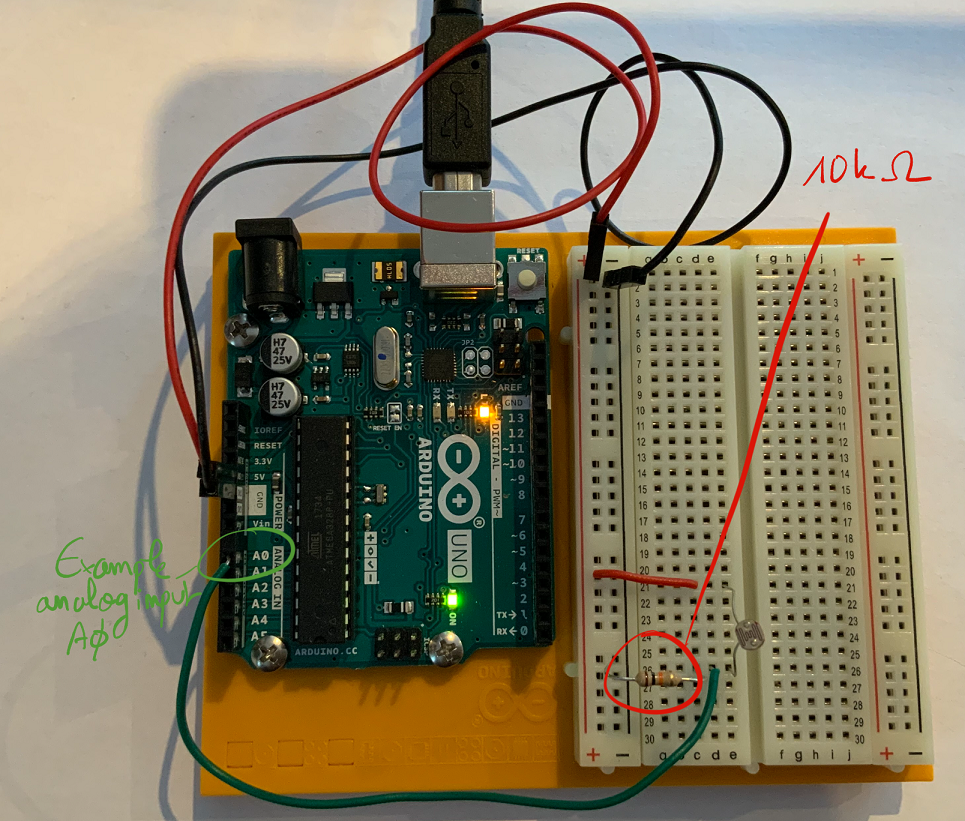
Figure 6.19: Connecting a photoresistor to an analog pin on the Arduino UNO board.
An example of arduino code that could be uploaded in the microcontroller is shown below. In this example, the analog input A0 catch the value of the sensor. The value that is between 0 and 1023 is a representation of the voltage on the pin.
1 2 3 4 5 6 7 8 9 10 11 12 13 14 | void setup() {
Serial.begin(9600); // initialize serial communications at 9600 bps:
}
void loop() {
int sensorValue; // value read from the voltage divider (resistor + photoresistor)
sensorValue = analogRead(A0); // read the analog in value
// print the results to the Serial Monitor:
Serial.print("sensor = ");
Serial.print(sensorValue);
Serial.print("\n");
delay(1000); //Wait 1000 ms before the next loop
}
|
The value is printed on the serial connection between the board and the computer. It can be observed using the serial monitor (“Tools” -> “Serial monitor” in the Arduino application).
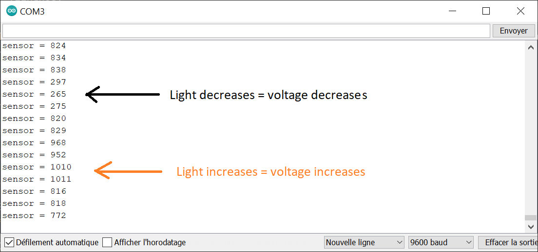
Figure 6.20: The serial monitor shown the value catch by the analog input each 1000 ms. The value ranges from 0 (nul voltage) to 1023 (5V).
6.3.5. Servo motor
6.3.5.1. Presentation
A servo motor is a special type of motor that don’t spin around a circle. It can move to a sepcific position and keep it. Servos usually only rotate 180 degrees.
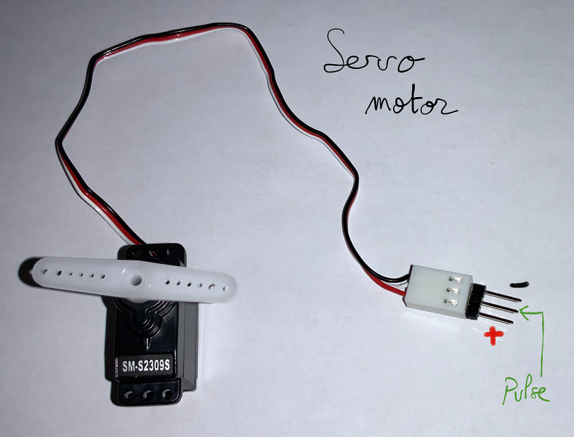
Figure 6.21: The servo motor in the kit.
6.3.5.2. Example using Arduino
Connection to a analog pin to catch the voltage is possible with Arduino UNO board.
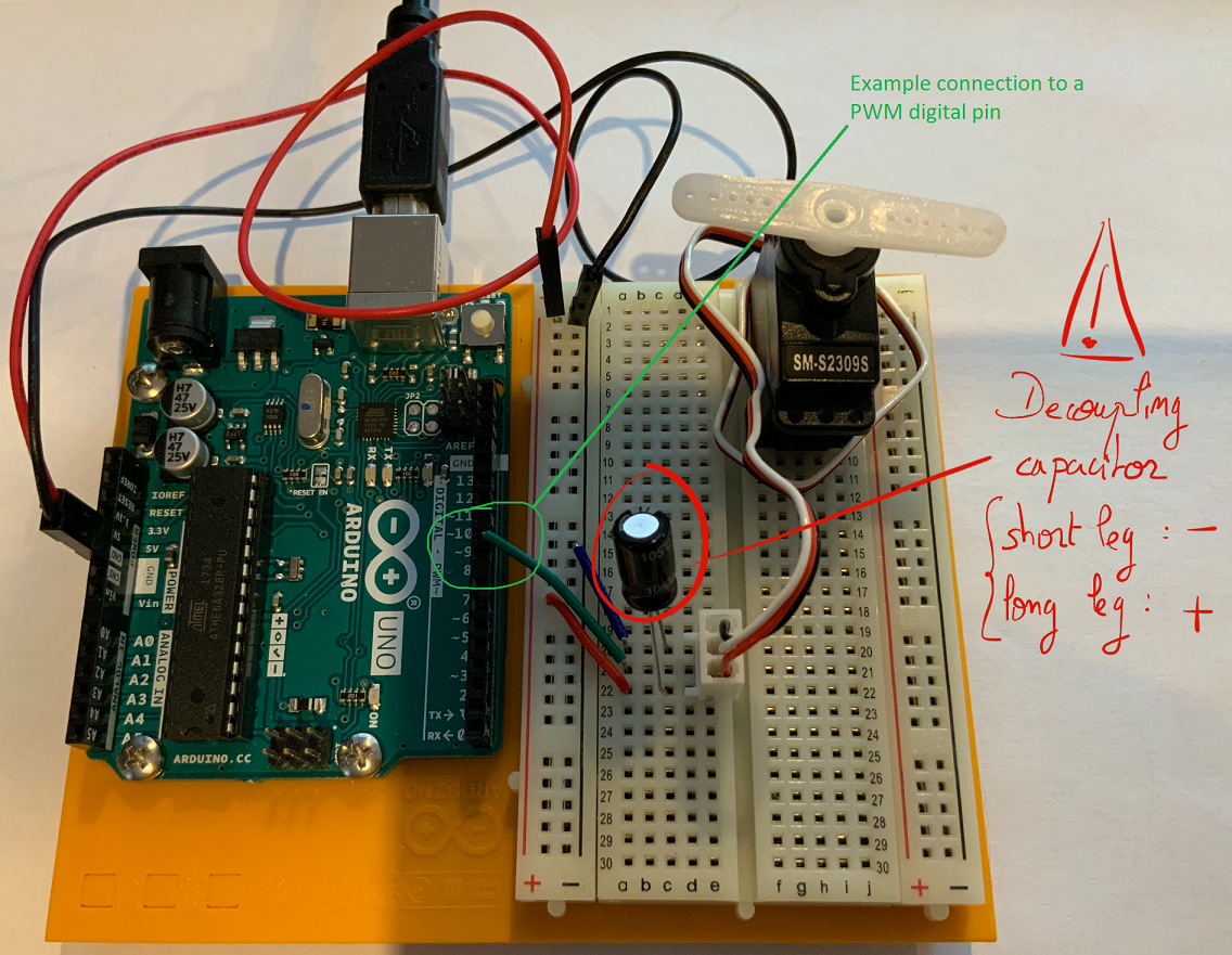
Figure 6.22: Connecting a servo to a digital PWM pin on the Arduino UNO board.
Caution
A decoupling  capacitor is used to reduce voltage changes when the motor start and stop. The capacitor anode (long leg) must be connected to power and the cathode (short leg) to the ground to prevent explosion of the component.
An example of arduino code that could be uploaded in the microcontroller is shown below. In this example, the analog PWM output 9 is used to send pulse to the servo. The arduino code uses the library servo. This library allows to specify directly an angle between 0 and 179 degrees to the servo.
1 2 3 4 5 6 7 8 9 10 11 12 13 | #include <Servo.h>
Servo servo;
void setup() {
servo.attach(9); //The servo is attached to digital pin 9
}
void loop() {
servo.write(0);
delay(2000);
servo.write(179);
delay(2000);
}
|
6.3.6. Piezo
6.3.6.1. Datasheet
6.3.6.2. Presentation
A piezo is an electrical component used to detect vibrations (input) or produce noises (output). The piezo in the Arduino UNO starter kit is a PKM22EPP-4005-B0.
6.3.6.3. Connections using Arduino
The piezo can be connected as input or output using the Arduino UNO board.
6.3.6.3.1. Piezo as input
The piezo can detect vibration as knocks, that can be catch by the Arduino board through an analog input.
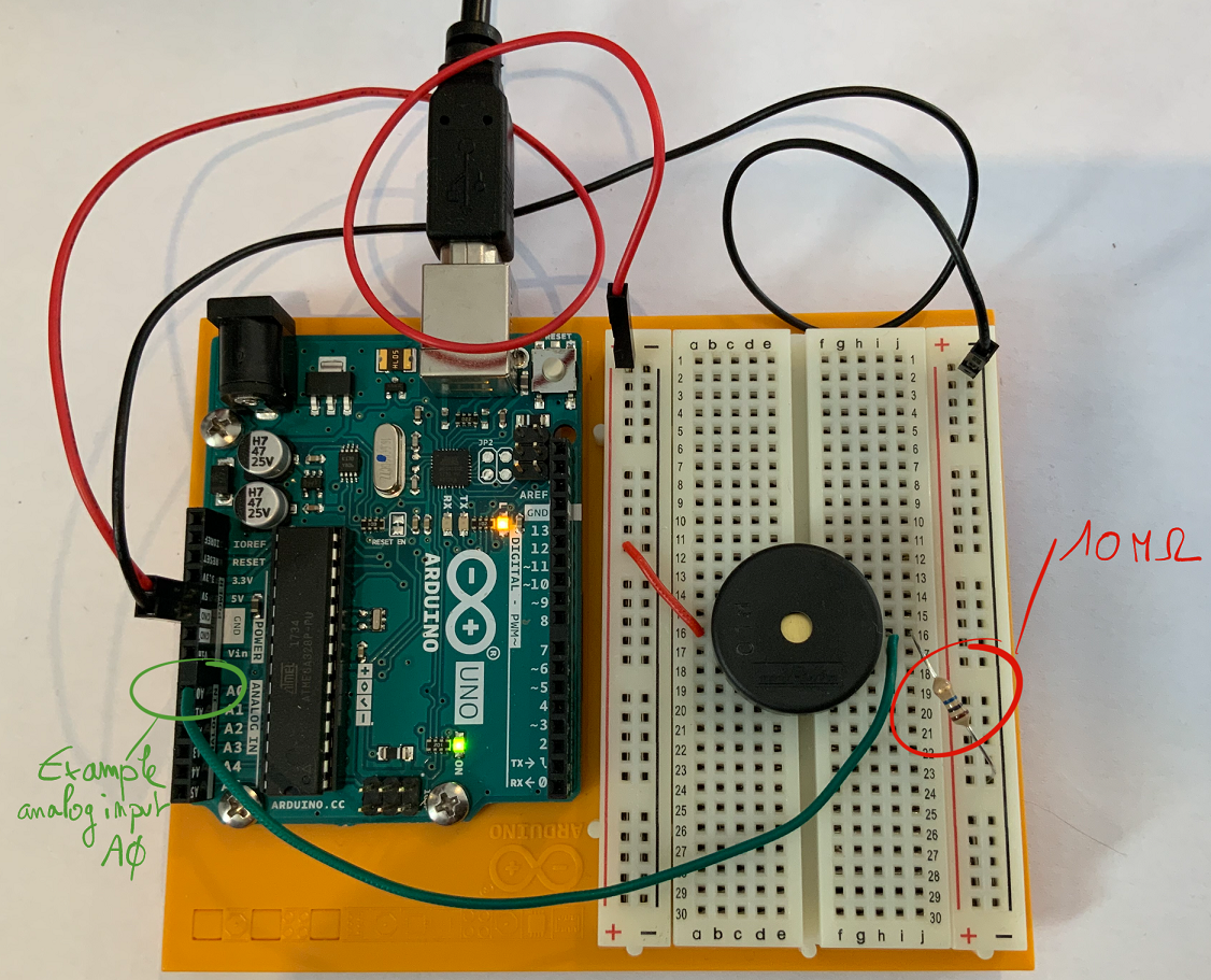
Figure 6.23: Connecting a Piezo to detect vibrations.
An example of arduino code that could be uploaded in the microcontroller is shown below. In this example, the analog input A0 is used to detect the piezo vibrations.
1 2 3 4 5 6 7 8 9 10 11 12 | int piezoValue;
void setup() {
Serial.begin(9600); //begin serial connection for monitoring
}
void loop() {
piezoValue = analogRead(A0);
Serial.print("piezo value ");
Serial.println(piezoValue);
delay(600);
}
|
The value is printed on the serial connection between the board and the computer. It can be observed using the serial monitor (“Tools” -> “Serial monitor” in the Arduino application).
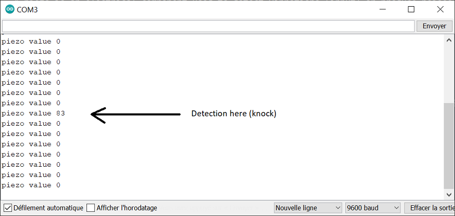
Figure 6.24: The serial monitor shown the value catch by the analog input each 600 ms. A change in value is observed when a knock is detected.
6.3.6.3.2. Piezo as output
Emitting sounds is possible with the piezo by direct connection to a digital pin.
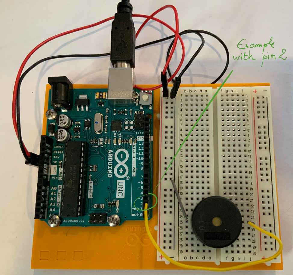
Figure 6.25: Connecting a Piezo as output to emit sounds.
An example of arduino code that could be uploaded in the microcontroller is shown below. In this example, the digital output 2 is used to connect the piezo.
1 2 3 4 5 6 7 8 9 10 | void setup() {
//No specific setup when using the tone function on an input
}
void loop() {
tone(2, 440, 1000); // Play a 440Hz A during 1 sec on pin 2
delay(1050);
tone(2, 494, 1000); // Play a 494Hz B during 1 sec on pin 2
delay(1050);
}
|
The tone(int digitalPin, int frequency, int duration) function is adpated to the piezo utilisation and takes 3 arguments: the pin, the frequency (Hz) and the duration (ms). This command sends pulses to the pin at 50% duty cycle (half the time the pin in HIGH, the other half the time it is low) but with a custom frequency.
Note
This is different to PWM analogWrite(int PWMPin, int value) function where the frequency is fixed, but the duty cycle changes (from 0 to 100% corresponding to a value between 0 and 255).